Pipeline Erosion & CFD Erosion Analysis

Predicting and Mitigating Material Wear in Fluid Systems

ENA2 provides pipeline erosion analysis and CFD erosion analysis services to predict material wear caused by solid particles, sand, and slurry flowing through pipelines and process equipment. Using CFD-based particle tracking and erosion models, we evaluate particle trajectories, impact velocity, impact angle, and erosion-prone regions to support pipeline design, material selection, integrity assessment, and maintenance planning.

Pipeline Erosion Analysis

Pipeline erosion occurs when abrasive particles carried by gas, liquid, or slurry repeatedly impact internal pipe surfaces. The risk can increase around elbows, bends, reducers, tees, valves, fittings, and other flow disturbances. ENA2 uses CFD-based particle tracking to identify areas where particle concentration, velocity, impact angle, and flow patterns may contribute to accelerated material wear.

Pipeline erosion analysis can support:

  • Identification of erosion-prone pipeline locations
  • Evaluation of particle impact behavior
  • Comparison of alternative geometries and operating conditions
  • Assessment of slurry and sand-laden flow conditions
  • Material, coating, and liner selection
  • Pipeline inspection and maintenance planning

Simulation Capabilities

Eulerian–Lagrangian or DPM-Based Particle Tracking

Using the Discrete Phase Model (DPM) or Eulerian–Lagrangian approach, we simulate:

  • Particle trajectories based on fluid velocity, drag, gravity, and turbulence dispersion.
  • Impact angle and velocity on surfaces to assess erosion severity.
  • Steady or transient flow conditions, capturing unsteady particle-wall interactions in pulsating or start-up scenarios.

This modeling approach is ideal for analyzing sand-laden flows, ash particles, water droplets in steam systems, or solid contaminants in pipelines and vessels.

Eulerian-Lagrangian discrete phase model for particle transport in CFD.
CFD erosion rate model showing predicted material loss.
Erosion Rate Models

ENA2 integrates industry-validated erosion correlations to calculate material loss over time:

  • Oka model – suitable for high-velocity gas-solid flows with size and angle dependency.
  • Finnie model – appropriate for ductile materials and low-velocity erosion scenarios.
  • DNV-RP-O501 – widely used for offshore oil and gas systems handling sand production.

These models account for factors like impact velocity, particle size and hardness, fluid carrier properties, impingement angle, and material erosion resistance to deliver actionable predictions for material selection and design improvements.

Pipeline Erosion Prediction

CFD-based pipeline erosion prediction helps engineers identify potential wall-loss locations before significant material damage occurs. By combining flow-field results with discrete particle tracking and erosion-rate models, the analysis can indicate where particles are most likely to impact pipeline surfaces and where erosion may be concentrated.
Prediction results can be used to compare operating conditions, evaluate design alternatives, identify high-risk components, and support inspection or maintenance decisions.

Multiphase CFD erosion analysis on an industrial pipe bend.
Multiphase Flow Erosion

ENA2 simulates erosion in gas-solid, liquid-solid, or steam-droplet flow environments, allowing us to assess wear in:

  • Oil and gas pipelines, particularly in elbows, bends, and valves where sand particles are common.
  • Steam turbines and condensers, where wet steam droplets cause droplet impingement erosion.
  • Hydrotransport systems, involving slurry or abrasive liquid-solid flows in mining or chemical processing.

By modeling interphase interactions, we can accurately predict particle concentration zones, stagnation regions, and turbulent eddies that accelerate wear.

Geometry-Specific Wear Assessment

We compute:

  • Local losses: Across valves, orifices, or fittings using CFD-derived K-factors
  • System-wide losses: Total pressure drop over long piping runs, ducting systems, or equipment arrays

This allows identification of critical loss locations and opportunities for redesign or optimization.

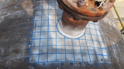
Geometry-specific wear zone on an industrial piping component.

Causes and Mechanisms of Erosion

Erosion typically results from high-velocity particles impacting surfaces within fluid systems. Our analysis captures the underlying mechanisms:

Solid Particle Impingement

Hard particles in liquid or gas streams striking walls at high velocity and varying angles cause localized wear.

Liquid Droplet Impingement

High-speed liquid droplets in steam or mist flow regimes impacting metallic surfaces can cause droplet erosion.

Slurry Flow-Induced Erosion

Suspended particles in dense-phase slurry flow produce erosion in bends, reducers, tees, and valves.

Cavitation-Driven Erosion

Localized collapse of vapor bubbles near solid boundaries generates intense pressure spikes leading to pitting damage.

CFD Erosion Analysis Services

  • Pipeline Erosion Analysis — Evaluate particle-induced wear in pipelines, bends, fittings, and connections.
  • Particle Erosion Analysis — Assess particle trajectories, impact velocity, impact angle, and erosion rate.
  • Slurry Erosion Analysis — Evaluate abrasive slurry flow through pipelines and process components.
  • Erosion Risk Assessment — Identify high-risk regions and compare operating or design conditions.
  • Design & Material Evaluation — Compare geometry, coatings, liners, and material options where applicable.

Evaluation Metrics and Deliverables

Our erosion simulations provide critical engineering insights, including:

  • Particle trajectory maps and impact velocity profiles
  •  Erosion rate contours and cumulative material loss prediction
  • Identification of critical wear zones and erosion damage timelines
  • Design improvement recommendations (geometry, coatings, flow conditioning)
  • Comparative studies between materials, flow velocities, and particle characteristics

Applications and Industry Use

ENA2’s erosion analysis helps clients design more durable systems, reduce maintenance frequency, and prevent operational failures. With physics-based modeling and validated empirical methods, we ensure accurate predictions of erosion behavior in even the most demanding flow environments.

Engineering Results

CFD Erosion Analysis Case Study

FAQ

Erosion Analysis FAQs

Common questions about CFD erosion analysis for pipelines, components, operating conditions, design evaluation, and maintenance planning.

Interested in Erosion Analysis?
Design more durable systems and prevent

operational failures with our expert

erosion analysis solutions.
Scroll to Top