
Pressure Drop Analysis for Pipelines & Piping Systems
Optimizing Fluid Systems for Energy Efficiency and Performance
ENA2 provides CFD-based pressure drop analysis for piping systems, pipelines, process equipment, heat exchangers, and HVAC applications. Our pressure drop calculations and flow simulations evaluate frictional and local losses, flow distribution, and pressure variations to support equipment sizing, system optimization, and energy-efficient design.
Pipeline and Piping Pressure Drop Analysis
ENA2 performs CFD-based pressure drop analysis for pipelines and piping systems to evaluate frictional losses, local pressure losses, flow resistance, and pressure distribution. The analysis can account for valves, bends, tees, reducers, expansions, contractions, filters, nozzles, and other flow restrictions to identify pressure-loss locations and support piping design, flow balancing, and equipment sizing.
Simulation Capabilities
Detailed Geometric Modeling
We construct 3D models that faithfully represent all pressure-affecting features in your system:
- Valves (open, throttled, or closing)
- Elbows, tees, reducers, diffusers
- Sudden expansions/contractions
- Internals, screens, nozzles, filters, or flow obstructions
This ensures realistic prediction of both major and minor pressure losses.
Steady-State and Transient Flow Analysis
- Steady-State Analysis – Used to simulate continuous flow under constant boundary conditions, providing pressure drop estimation at a fixed operating point. Ideal for evaluating flow resistance in straight runs, fittings, and branching components of pipes, ducts, or channels.
- Transient Flow Analysis – Applied to capture unsteady flow behavior and time-varying pressure losses during events such as valve closures, pump startups/shutdowns, dam gate movements, or abrupt demand shifts.
Additionally, we model pressure fluctuations and localized drop caused by vortex shedding, especially behind bluff bodies, flow obstructions, or abrupt geometry changes. Vortex-induced oscillations can lead to periodic pressure drop variations, flow instabilities, noise, and vibration in ducted or piped systems.
These transient simulations help predict real-world performance beyond steady conditions, ensuring safe and resilient system design even under fluctuating or disturbed flow regimes.
Multiphase Pressure Drop
Our solvers handle complex multiphase flows, including:
- Gas-liquid flows (e.g., condensate lines, compressor suction)
- Solid-liquid slurries (e.g., mining or wastewater systems)
- Steam-water mixtures in power systems
We model slip velocities, interfacial drag, and phase interactions to capture realistic pressure drop in non-homogeneous flows.
Local and System-Wide Pressure Loss
We compute:
- Local losses: Across valves, orifices, or fittings using CFD-derived K-factors
- System-wide losses: Total pressure drop over long piping runs, ducting systems, or equipment arrays
This allows identification of critical loss locations and opportunities for redesign or optimization.
Non-Newtonian and Compressible Fluids
Our simulations cover:
- Non-Newtonian flows such as slurries, polymers, and blood analogs, incorporating shear-dependent viscosity models
- Compressible flows, including high-speed gases or steam, where density and Mach number significantly influence pressure drop
We implement appropriate turbulence and compressibility models for accurate representation.
Importance of Pressure Drop Assessment
Whether in a new design or an existing system, pressure drop influences performance, safety, and cost. Our analysis supports:
Pump and Fan SizingÂ
Ensuring accurate head requirement calculation and energy-efficient selection
Flow Distribution BalancingÂ
Verifying uniform flow across multiple branches or devices
Equipment Sizing and RatingÂ
Supporting rating calculations for valves, filters, exchangers, and separators
Operational EfficiencyÂ
Minimizing energy losses due to friction, fittings, or poorly designed flow paths
Pressure Drop Analysis Results and Deliverables
Our pressure drop analysis provides engineering results that help clients validate system performance, identify pressure-loss locations, and optimize fluid-flow systems.
- Pressure drop vs. flow rate curves for components or systems
- Frictional and minor loss contributions (K-factors)
- Velocity and pressure contour plots for visual assessment
- Impact of flow regime (laminar/turbulent/transitional) on pressure losses
- Recommendations for flow path improvement, size adjustment, or energy efficiency
Why Choose ENA2 for Pressure Drop Analysis?
- CFD and engineering expertise
- Experience with complex flow systems
- Multiphase and compressible-flow capabilities
- Relevant industry experience
- Engineering analysis and reporting capabilities
- Software/solver expertise, where appropriate
Industries We Serve
By combining CFD accuracy with practical engineering insights, ENA2 enables clients to minimize pressure-related inefficiencies, avoid under- or oversizing, and ensure robust system design that meets performance expectations and safety margins.
Building, Facility & Construction
Structural Analysis, FEA & HVAC CFD

Infrastructure, Energy & Materials
Piping Stress, Water Hammer & CFD

Manufacturing & Industrial Equipment
Mechanical FEA, CFD & Fatigue Analysis

Aerospace & Defense
Structural FEA, CFD & Thermal Analysis

Transportation & Mobility
Crash Simulation, Fatigue & Thermal Analysis
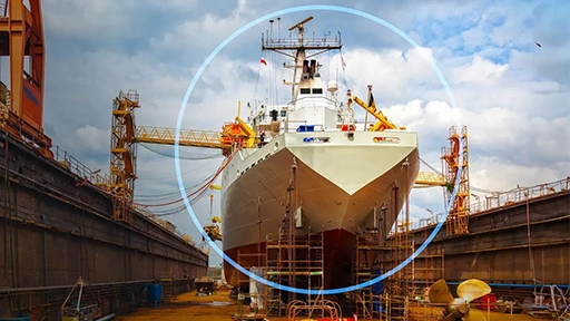
Marine & Offshore
Offshore FEA, Piping Stress & CFD

Life Sciences & Healthcare
Medical Device FEA & Cleanroom CFD

Consumer Packaged Goods
Packaging FEA & Process CFD
ENA2’s erosion analysis helps clients design more durable systems, reduce maintenance frequency, and prevent operational failures. With physics-based modeling and validated empirical methods, we ensure accurate predictions of erosion behavior in even the most demanding flow environments.
Case Studies
Structural Integrity
Structural Integrity Assessment of ERW Seam Flaws
Structural FEA
Improving Lateral Stiffness of Composite Wall Systems Through Vertical Reinforcement
Impact Analysis
Frontal Impact Assessment of Driver Cabin in Bus Structure
Nonlinear FEA
3D Nonlinear FEA Analysis of Pin-Column Connection
CFD Erosion
CFD Analysis for Predicting Erosion due to Slurry in Spoolable Pipe Connection
Fitness-for-Service
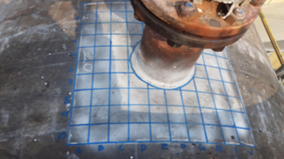
Fitness-For-Service Assessment of DEA Reboiler
Fatigue Assessment
Fatigue Life Assessment of a Blow-Case Pressure Vessel
Dynamic Stress
Flow-Induced Dynamic Stress and Fatigue Analysis of an Industrial Manifold Assembly
Pressure Drop Analysis FAQs
Common questions about CFD pressure drop analysis for pipelines, piping systems, complex flow conditions, system design, and engineering evaluation.
CFD is particularly useful when pressure-drop behaviour is influenced by complex geometries, multiple components, flow restrictions, transient operating conditions, or multiphase and compressible flows. It provides detailed pressure and velocity distributions that help identify localized losses and flow behaviour that may not be fully captured through simplified calculations.
Pipeline pressure drop generally refers to pressure loss along a pipeline used to transport fluids over a distance, while piping pressure drop can include losses throughout a more complex piping network containing branches, valves, fittings, and equipment connections. CFD can be used to evaluate pressure distribution and flow resistance in both applications.
Depending on the project requirements, deliverables can include pressure-drop versus flow-rate curves, pressure and velocity contours, frictional and minor loss contributions, CFD-derived K-factors, flow-regime assessment, and recommendations for flow-path or system improvements.
Yes. ENA2 can analyze complex multiphase flows such as gas-liquid flows, solid-liquid slurries, and steam-water mixtures. CFD simulations can account for phase interactions, slip velocities, and interfacial effects to evaluate pressure drop under non-homogeneous flow conditions.
Typically, a CFD pressure drop analysis may require the system geometry, fluid properties, flow rate or velocity, inlet and outlet conditions, operating pressure and temperature, pipe roughness, and relevant component information. Additional inputs may be required for compressible, multiphase, or transient flow conditions depending on the application.
Yes. CFD can be used to compare pipe diameters, routing options, valves, fittings, reducers, manifolds, flow restrictions, and operating conditions to determine how design changes affect pressure loss and flow distribution. The results can help identify sources of excessive pressure drop and evaluate potential system improvements before implementation.