
CFD Analysis of a Shell-and-Tube Heat Exchanger
Learn how Computational Fluid Dynamics (CFD) can be used to evaluate tube-side and shell-side flow distribution, pressure drop, conjugate heat transfer, tube-wall temperature, and thermal gradients in a counter-flow shell-and-tube heat exchanger.
Article Sections
What Does CFD Evaluate Inside a Counter-Flow Heat Exchanger?
A heat exchanger can meet its required inlet and outlet conditions while still developing non-uniform flow, localized pressure losses, or important temperature variations inside the equipment.
For engineers, understanding these internal conditions can be just as important as knowing the overall heat-transfer rate. How is the flow distributed through the tubes and shell? Where does pressure drop develop? How does temperature change through the fluids and tube walls?
A three-dimensional Computational Fluid Dynamics (CFD) model can help answer these questions by predicting the internal velocity, pressure, and temperature fields under defined operating conditions.
Evaluate tube-side and shell-side flow trajectories, flow patterns, and velocity distributions.
Determine the pressure drop across the tube side and shell side of the heat exchanger.
Evaluate temperature variations and heat transfer between the tube-side and shell-side fluids across the tube walls.
Evaluate temperature distributions and thermal gradients across the tube walls, tubesheets, shell, and other critical components for subsequent FEA analysis.
A heat exchanger is a coupled flow and heat-transfer system: the way the fluids move influences heat transfer, while the geometry that guides the flow also affects the pressure required to maintain it.
How Counter-Flow Works in a Shell-and-Tube Heat Exchanger
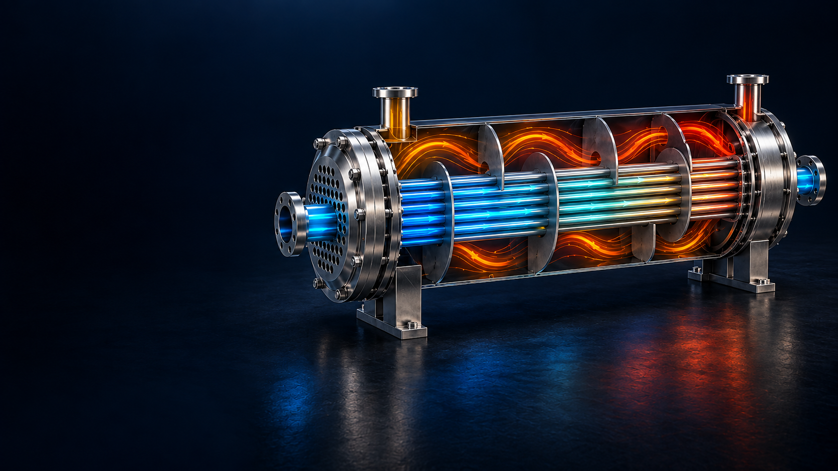
In a counter-flow arrangement, the hot and cold fluid streams progress in generally opposing directions. This arrangement helps maintain the temperature driving force along the exchanger length and can provide a stronger thermal driving force than parallel flow under comparable conditions.
In a shell-and-tube heat exchanger, one fluid passes through the tubes while the other flows through the shell surrounding them. The overall exchanger can be counter-current even though the local shell-side path may turn, accelerate, decelerate, or move across the tube bundle as it follows the available geometry.
This distinction matters because the overall flow arrangement describes the exchanger at system level, while CFD resolves the local flow field that actually governs convection and hydraulic loss.
Conceptual illustration only. The actual CFD model resolves the local flow direction, recirculation, acceleration, and distribution created by the exchanger geometry.
Evaluating Tube-Side and Shell-Side Flow Distribution
A specified inlet flow rate does not mean that velocity remains uniform throughout a heat exchanger. As the fluids enter the equipment and move around the internal geometry, both the available flow area and the local flow direction can change.
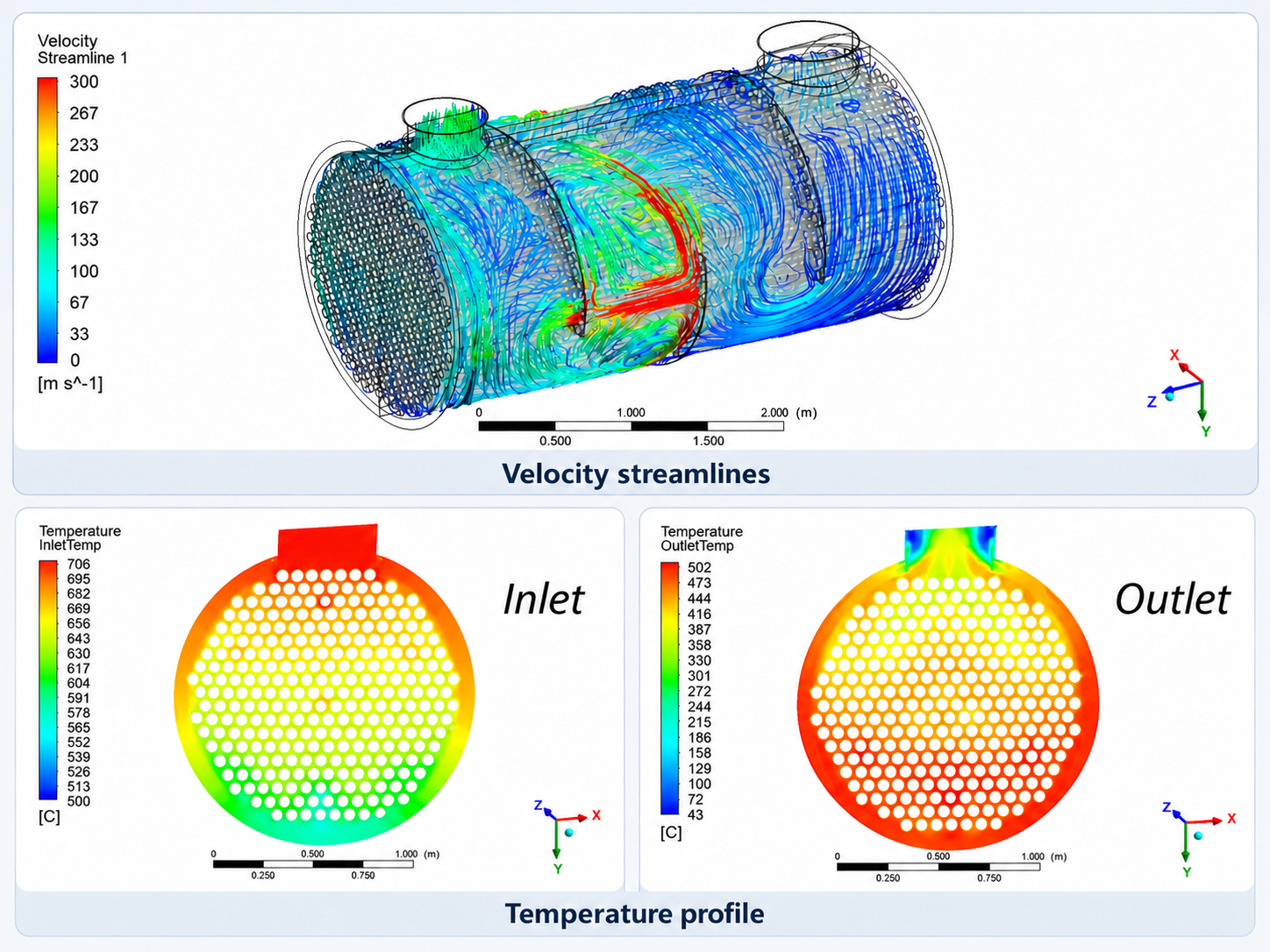
The resulting flow field may contain regions of acceleration, deceleration, recirculation, bypassing, or comparatively low velocity. CFD resolves this velocity field throughout the model so these local patterns can be examined directly rather than inferred from a single bulk flow rate.
On the tube side, the analysis can show how flow is distributed through the available tube passages. On the shell side, velocity contours and streamlines can show how fluid moves around the tube bundle and through the available shell-side flow area.
Where Does Pressure Drop Develop in a Heat Exchanger?
Fluid moving through a heat exchanger must overcome resistance associated with wall friction, restrictions, changes in flow area, changes in direction, and internal geometry. The result is a pressure difference between the inlet and outlet.
Pressure drop is therefore more than a post-processing value. It represents the hydraulic resistance that must be overcome to maintain the intended flow rate and should be evaluated separately for the tube-side and shell-side flow paths.
The engineering objective is not simply to minimize pressure drop or maximize local velocity. It is to understand the balance between thermal performance and the hydraulic resistance required to achieve it.
Connecting Fluid Flow and Heat Transfer Through the Tube Walls
Heat transfer within the exchanger involves both the fluids and the solid tube walls that separate them. Energy is transferred by convection from one fluid to the tube surface, conducted through the tube material, and then transferred by convection to the fluid on the opposite side.
A CFD model that includes the fluid regions and solid tube walls can represent these mechanisms together through conjugate heat transfer (CHT). In practical terms, CHT models convection in the fluids together with conduction through the solid material.
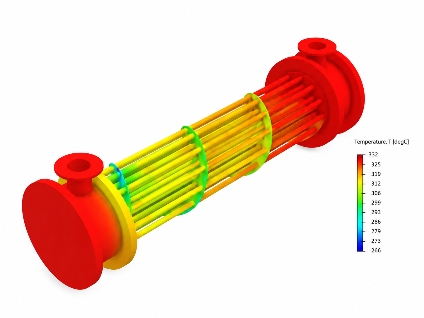
The resulting temperature field provides more information than inlet and outlet temperatures alone. It shows where temperature changes spatially and provides the thermal field that can later inform a separate structural thermal-stress assessment.
Evaluating Tube-Wall Temperature and Thermal Gradients
Temperature distribution and thermal gradient are related, but they describe different quantities. The temperature distribution describes the temperature at different locations within the exchanger. A thermal gradient describes how rapidly temperature changes from one location to another.
In heat exchanger tubes, temperature can vary along the tube length, around the circumference, and through the wall thickness as energy moves between the two fluid streams. Including the solid tubes in the conjugate heat-transfer model allows these spatial variations to be evaluated directly.
A larger temperature change over a shorter distance produces a steeper local thermal gradient. Figure 2 provides the temperature field from which those spatial variations can be interpreted.
A thermal gradient is not thermal stress. CFD or CHT predicts the temperature field; structural stress is obtained only after the temperature field is applied within a structural model that accounts for material behaviour, geometry, and restraint.
If thermal stress is an engineering concern, the predicted temperature field can be transferred to a separate finite element thermal-stress analysis. That structural assessment can then evaluate how thermal expansion and restraint translate the temperature field into deformation and stress.
How Are Heat Exchanger CFD Results Checked?
Detailed CFD contours are useful only when the underlying numerical model provides a credible representation of the engineering problem. Appropriate geometry, fluid and material properties, boundary conditions, mesh resolution, turbulence modelling, and numerical settings all contribute to the quality of the prediction.
Solver convergence is one part of this process, but it is not the only check.
- Mass conservation through the fluid domains
- Energy balance between the hot and cold streams
- Stability of calculated pressure drop
- Stability of outlet-temperature predictions
- Mesh-sensitivity assessment
- Comparison with test data, design calculations, or established engineering correlations where available
These checks help establish whether the numerical results are sufficiently consistent for the engineering question being evaluated. CFD should therefore be treated as an engineering analysis tool rather than simply a method for generating contour plots.
Verification and Validation in Computational Fluid Dynamics and Heat Transfer; useful context for separating numerical verification from validation.
Mass, energy, pressure-drop, outlet-temperature, and mesh-sensitivity checks provide numerical evidence beyond solver convergence alone.
Where available, compare CFD outputs with test data, design calculations, or established correlations appropriate to the exchanger and operating condition.
See the Counter-Flow Heat Exchanger CFD Analysis in Practice
From CFD Contours to Engineering Interpretation
ENA2's engineers will examine the CFD modelling of a counter-flow heat exchanger and discuss how velocity, pressure drop, temperature distribution, and tube-wall thermal gradients can be interpreted as part of an engineering assessment.
Counter-Flow Heat Exchanger CFD FAQ
Answers to common engineering questions about shell-and-tube heat exchanger CFD, flow distribution, pressure drop, conjugate heat transfer, and thermal gradients.
What can CFD predict in a shell-and-tube heat exchanger?
CFD can predict the internal velocity, pressure, and temperature fields of a shell-and-tube heat exchanger under defined operating conditions. These results can be used to evaluate flow distribution, pressure drop, heat-transfer behaviour, and local temperature variation.
Why is counter-flow used in heat exchangers?
In a counter-flow arrangement, the hot and cold fluids move in generally opposite directions. This helps maintain a useful temperature difference between the streams along the exchanger and can provide a stronger temperature driving force than parallel flow under comparable conditions.
How is pressure drop evaluated with CFD?
CFD calculates the pressure field throughout the fluid domain. The difference between appropriate inlet and outlet pressure values can be used to determine overall pressure drop, while pressure contours help show where hydraulic losses develop inside the exchanger.
What is conjugate heat transfer in a heat exchanger simulation?
Conjugate heat transfer, or CHT, models heat transfer in both fluid and solid regions. For a shell-and-tube exchanger, this means modelling convection in the tube-side and shell-side fluids together with heat conduction through the tube walls.
Why are thermal gradients in heat exchanger tubes important?
Thermal gradients describe how temperature changes through or along the tube material. Evaluating these gradients helps engineers understand where larger temperature variations occur and whether additional thermal or structural assessment may be appropriate.
Can CFD calculate thermal stress in heat exchanger tubes?
A thermal CFD or conjugate heat-transfer analysis calculates the temperature field, not structural stress by itself. When thermal stress must be evaluated, the predicted temperature distribution can be applied as thermal loading in a separate structural finite element analysis.
How can engineers check whether a heat exchanger CFD model is reliable?
Typical checks include monitoring numerical convergence, confirming mass and energy conservation, evaluating mesh sensitivity, and comparing calculated quantities such as pressure drop or outlet temperatures with available test data, design calculations, or established engineering correlations.