
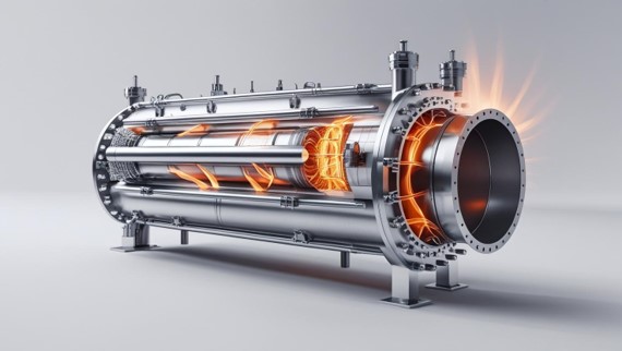
Transient Thermal Stress Analysis of a Heat Exchanger
See how temperature fields from computational fluid dynamics (CFD) can be transferred into structural finite element analysis (FEA) to evaluate thermal gradients, thermal expansion, deformation, and stress in a shell-and-tube heat exchanger.
Article Sections
How Does a Temperature Field Become Thermal Stress?
A temperature contour can show where a heat exchanger is hot or cold. It does not, by itself, show how the structure responds to those temperatures.
During a thermal transient, different regions of a heat exchanger can heat or cool at different rates. Those temperature differences cause the material to expand by different amounts. When that expansion is restricted by the surrounding structure, supports, connections, or adjacent regions at different temperatures, mechanical stresses can develop.
The structural analysis therefore begins with the temperature field and follows the response through thermal strain, deformation, and stress.
Use the CFD-derived temperature distribution as the thermal input for the transient structural analysis.
Evaluate where temperature changes most strongly through or along the structure.
Determine how the vessel attempts to expand, contract, bend, or distort.
Identify where restrained or incompatible thermal expansion concentrates structural response.
Temperature is the thermal loading; stress is the structural response. The highest temperature is not necessarily the most critical structural condition.
With this thermal-stress mechanism established, the webinar applies the workflow to the same counter-flow shell-and-tube heat exchanger evaluated in the companion CFD study. The CFD analysis is performed in Ansys Fluent to obtain the temperature distribution, while the transient thermal-stress FEA is performed in Abaqus using the relevant CFD-derived temperature information as the thermal input for evaluating the response of the heat exchanger vessel.
Transferring the CFD Temperature Field Into Structural FEA
The companion CFD analysis is performed in Ansys Fluent to resolve the flow and temperature distribution of the counter-flow shell-and-tube heat exchanger. The relevant temperature information is then used to define the thermal loading for ENA2's mechanical finite element analysis of the vessel.
CFD and structural models are discretized for different purposes. The CFD mesh is developed around fluid flow and heat transfer, while the structural mesh must represent stiffness, restraints, contact, geometric discontinuities, and stress gradients. The temperature information therefore has to be transferred or applied in a way that preserves the spatial variation relevant to the structural response.
For the webinar analysis, the transient thermal-stress FEA is performed in Abaqus using the relevant CFD-derived temperature field as the thermal input. The structural model incorporates the applicable thermo-mechanical material properties and restraints so that deformation and thermal stress can be evaluated as the thermal condition evolves.
A transient thermal-stress analysis requires the structural model to represent how the thermal condition changes with time. The relevant CFD-derived temperature distribution provides the thermal basis for evaluating the evolving vessel response in Abaqus.
Why Spatial and Transient Temperature Gradients Matter
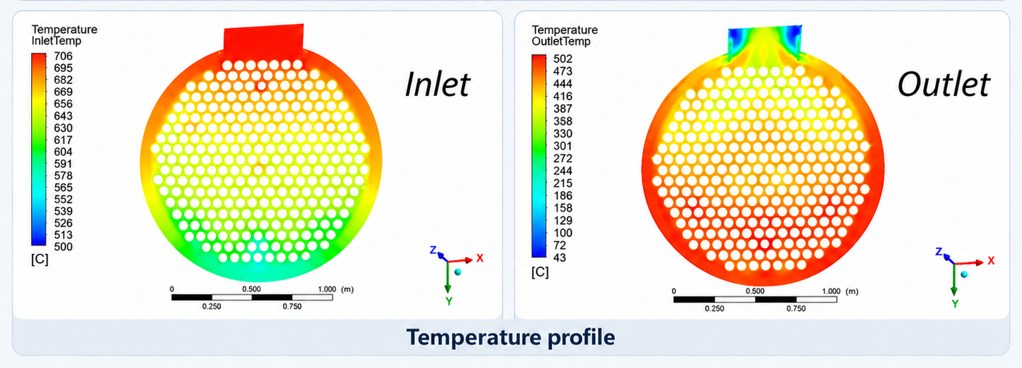
Figure 1 compares CFD temperature profiles at the inlet and outlet cross-sections of the heat exchanger. The contours show that the temperature field is non-uniform across both sections and that its spatial distribution changes between the two locations. This variation is important because structural thermal loading depends not only on the absolute temperature, but also on how temperature changes from one region of the structure to another.
The inlet and outlet views represent spatial snapshots at two locations; they should not be interpreted as a time history of the thermal transient. For a transient thermal-stress assessment, the relevant temperature field must also be considered as it evolves with time. The structural model therefore needs thermal information that preserves the spatial—and, where applicable, temporal—variation responsible for differential thermal expansion.
A larger temperature difference over a shorter distance produces a steeper local thermal gradient.
In a heat exchanger, thermal gradients can develop along the equipment, across a cross-section, and through structural thicknesses as different regions heat or cool at different rates.
For structural FEA, the relevant CFD temperature information must be applied to the corresponding structural domain in a way that preserves the thermal variation responsible for the mechanical response. The CFD visualization helps reveal where temperature differences exist, while the structural model determines how those differences translate into thermal strain, deformation, and stress.
The critical engineering question is therefore not simply how hot does the heat exchanger become? It is where the strongest temperature differences develop, how they change with time, and how the structure is restrained while they occur. The most demanding structural condition may occur before the equipment reaches its final operating temperature.
Maximum temperature and maximum thermal stress do not necessarily occur at the same time. Structural response depends on the evolving temperature gradients, material behavior, geometry, and restraint.
How Thermal Expansion Develops Into Structural Stress
Materials expand or contract as their temperature changes. For an isotropic material with an approximately constant coefficient of thermal expansion, the free thermal strain can be represented by a simple relationship.
Temperature change creates thermal strain. Stress develops when the resulting expansion is prevented or becomes incompatible with the surrounding structure.
If a component were heated uniformly and allowed to expand freely, it could develop thermal strain without a corresponding restraint-induced thermal stress. In an actual heat exchanger, restraint can come from vessel supports, tubesheet connections, nozzles, shell-to-head transitions, connected piping, contact, symmetry conditions, or other structural attachments. The same temperature field can therefore produce a different stress response depending on how the equipment is restrained.
A thermal-stress model is not defined by temperature alone. Boundary conditions determine how freely the heat exchanger can expand and strongly influence the resulting stress field.
Why Temperature-Dependent Material Properties Matter
A heat exchanger operating through a meaningful temperature range should not automatically be represented using one set of room-temperature mechanical properties. Material stiffness, thermal expansion, and strength can change as temperature changes.
The structural model should therefore use thermo-mechanical properties that are appropriate for the material, temperature range, and expected response. This is central to thermo-mechanical analysis, where temperature-dependent expansion, stiffness, and material response are represented according to the available data and modeling objective. Abaqus can define both thermal expansion and mechanical behavior as functions of temperature.
Not every property below is required for every analysis. The model should include only the behavior relevant to the expected temperature and stress range.
Converts temperature change into thermal strain.
Fundamental to thermal-expansion assessment.
Controls temperature-dependent stiffness and stress response.
When stiffness varies over the analyzed temperature range.
Influences multiaxial elastic deformation and stress.
Part of the elastic constitutive response.
Represents nonlinear material response beyond the elastic range.
When local or global stresses may approach yielding.
Represents time-dependent strain under sustained elevated temperature and stress.
Only where temperature and exposure duration make creep relevant.
The reference temperature is also part of the structural model because thermal strain is evaluated relative to a defined reference state. The selected reference should correspond to a physically meaningful condition for the equipment and analysis basis.
How the Applied Temperature Field Produces Deformation and Thermal Stress
Once the relevant temperature field is represented in the structural model, the analysis shifts from describing thermal conditions to evaluating mechanical response. Different regions of the heat exchanger attempt to expand or contract by different amounts as their temperatures change. Where that movement is restrained or becomes incompatible with adjacent regions, structural stresses develop.
In Abaqus, the resulting deformation and stress response depends on more than temperature alone. The analysis must also represent the reference temperature, thermal expansion behavior, temperature-dependent material properties where required, geometry, contacts, supports, connections, and other boundary conditions that control how freely the structure can move.
Structural results must therefore be interpreted in the context of the applied temperature field and the assumptions of the mechanical model. A local maximum on a stress contour should not automatically be described as a failure location. It may represent a meaningful structural response, a geometric stress concentration, a boundary-condition effect, or, in some cases, a numerical singularity. The result has to be interpreted together with the mesh, boundary conditions, material model, and applicable acceptance criteria.
During a transient, temperature differences can be greatest before the heat exchanger approaches a more uniform operating condition. The structurally critical time should therefore be identified from the evolving thermal and mechanical response rather than from the maximum absolute temperature alone.
Stress contours identify where structural response is concentrated and where further engineering assessment may be warranted. They do not, by themselves, demonstrate failure or establish compliance with an applicable design Code.
How Thermal-Stress FEA Fits Within an ASME Assessment
Shell-and-tube heat exchangers can form part of pressure-retaining systems governed by the applicable requirements of the ASME Boiler and Pressure Vessel Code, Section VIII.
ASME Section VIII, Division 1, Part UHX contains specific provisions for shell-and-tube heat exchangers, including configurations such as fixed-tubesheet, U-tube, and floating-head exchangers. Where a more detailed finite element Design-by-Analysis approach is used, ASME Section VIII, Division 2, Part 5 provides a framework for evaluating structural response and applicable failure modes.
This distinction matters because a finite element solver can calculate a stress field, but a stress contour alone does not establish Code compliance. Depending on the design basis, calculated stresses may need to be classified, evaluated against applicable limits, reviewed for the relevant failure mode, and—when repeated thermal cycling is important—considered within an appropriate fatigue assessment.
The applicable ASME edition, division, load combinations, stress-classification procedure, and acceptance criteria depend on the specific equipment and design basis. FEA results must be interpreted within that engineering framework.
How Is a CFD-to-FEA Thermal-Stress Model Checked?
Detailed structural contours are useful only when the underlying model provides a credible representation of the physical thermal-structural problem. Numerical convergence is necessary, but it is not the only check.
- Temperature-field transfer preserves the important spatial gradients
- Where a transient temperature history is used, the time-step resolution captures the critical part of the thermal event
- Structural mesh refinement does not materially change stresses of engineering interest
- Supports and constraints represent physical restraint without artificially locking thermal expansion
- Temperature-dependent material properties are appropriate for the analyzed range
- Initial and reference temperatures are defined consistently
- Localized stress peaks are distinguished from meaningful structural stress fields
- Results are compared with simplified calculations, design expectations, test data, or other engineering evidence where available
The objective is not simply to obtain a converged stress plot. It is to develop a model that represents the thermal loading, structural restraint, and material response with sufficient fidelity for the engineering question being evaluated.
See the Heat Exchanger Thermal-Stress Analysis in Practice
From Temperature Field to Structural Response
ENA2's engineers will connect the heat exchanger CFD temperature field with structural finite element analysis and discuss how transient thermal gradients, thermo-mechanical material behavior, structural restraint, deformation, and thermal stress can be interpreted as part of an engineering assessment.
Heat Exchanger Thermal Stress Analysis FAQ
Answers to common engineering questions about transient thermal stress, CFD-to-FEA temperature transfer, thermal gradients, structural restraint, material behavior, and Abaqus thermal-stress workflows.
What causes thermal stress in a heat exchanger?
Thermal stress develops when temperature changes cause different parts of the heat exchanger to expand or contract by different amounts and that thermal expansion is restrained or incompatible with the surrounding structure. Temperature gradients, geometry, supports, connections, and material properties all influence the response.
Is a thermal gradient the same as thermal stress?
No. A thermal gradient describes how temperature changes with position. Thermal stress is the mechanical response that can develop when the resulting thermal expansion is restrained or non-uniform.
How are CFD temperatures used in an FEA model?
Depending on the coupling workflow, CFD-derived thermal information can be mapped directly as a temperature field or used to define thermal loading for a subsequent transient thermal and structural analysis. The structural model then combines that loading with thermal-expansion properties, mechanical properties, geometry, and boundary conditions to calculate thermal strain, deformation, and stress.
Why is transient thermal-stress analysis important?
During startup, shutdown, or changing operating conditions, different parts of the equipment can heat or cool at different rates. The largest thermal gradients and the most significant structural stresses may therefore occur during the transient rather than at the final steady operating condition.
Does the highest temperature always produce the highest thermal stress?
No. Thermal stress depends on temperature differences, material expansion, structural restraint, geometry, and time. A lower absolute temperature with a steep local gradient can produce a more significant structural response than a higher but more uniform temperature field.
What material properties are important in thermal-stress FEA?
Important properties typically include the coefficient of thermal expansion, Young's modulus, and Poisson's ratio. Depending on the temperature and stress range, temperature-dependent yield or plasticity data and, where applicable, creep behavior may also need to be represented.
How does a CFD-to-FEA thermal-stress workflow work?
The CFD analysis resolves the temperature distribution, and the relevant thermal information is then mapped or applied to the structural model. Abaqus combines that thermal loading with material properties, geometry, contacts, supports, and other boundary conditions to calculate thermal strain, deformation, and stress as the thermal condition evolves.
Can Abaqus perform transient thermal-stress analysis?
Yes. Abaqus supports transient thermal analysis, temperature-dependent material properties, thermal expansion, field transfer between meshes, sequential thermal-stress workflows, and fully coupled temperature-displacement procedures when the physics requires simultaneous thermal and mechanical solution.