
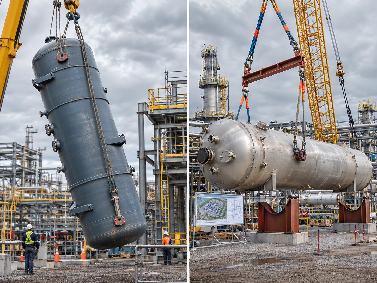
Lifting Lug and Trunnion FEA for a Heavy Tube Bundle Lift
ENA2 built detailed finite element models of the lifting lugs and trunnions on a heavy tube bundle, checked them at three positions through a horizontal-to-vertical lift under factored lifting loads, and developed strengthening for the overstressed regions in the existing design.
The Challenge: Rotating a Heavy Tube Bundle from Horizontal to Vertical
The lifting lugs and trunnions of a heavy tube bundle needed a structural assessment for lifting and rotation from horizontal to vertical. ENA2 assessed the existing designs with finite element analysis as part of its cranes, lifting and fall arrest systems engineering work.
As the bundle rotates, the load on each lug changes direction and out-of-plane loading appears, so a check at a single position may not capture the governing case. The designs were therefore assessed at several lifting positions under factored lifting loads.
Engineering Approach: Lifting Lug Analysis at 0°, 45° and 90°
-
01 Finite element models
ENA2 built detailed finite element models of the lifting lugs, the trunnions and the regions where they attach to the bundle.
-
02 Three lifting positions
The system was evaluated at 0°, 45° and 90° lifting positions. Loads were applied to represent bearing contact between the lifting components and the lifting pins or trunnions.
-
03 Factored loads and stress evaluation
The analysis incorporated factored lifting loads in accordance with ASME BTH-1. It evaluated stress distributions in the lug plates, attachment regions, trunnion pipe and supporting components.
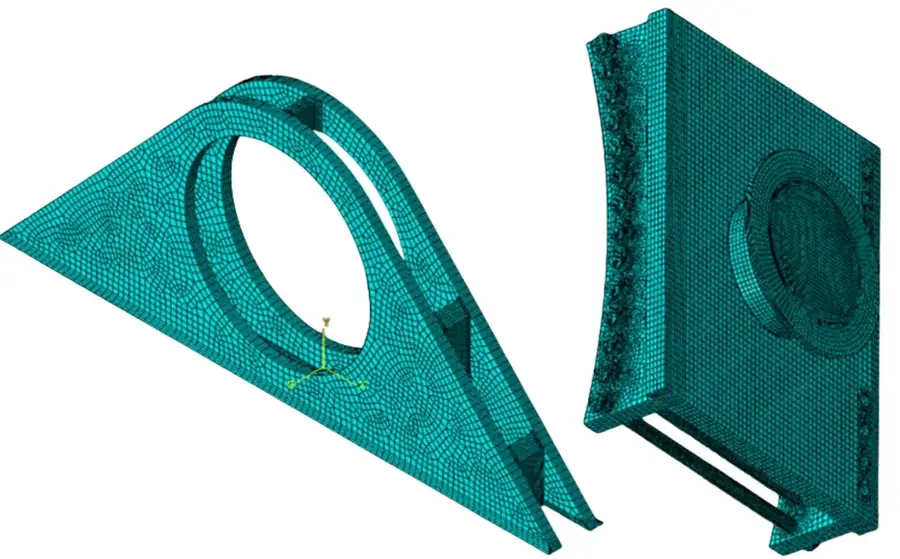
Challenge, Engineering Approach & Result
Challenge
Lugs and trunnions on a heavy tube bundle had to be verified for a lift that rotates the bundle from horizontal to vertical, with the load distribution changing at every angle.
Engineering Approach
ENA2 built detailed finite element models of the lugs and trunnions and evaluated them at 0°, 45° and 90° under factored lifting loads in accordance with ASME BTH-1, with bearing contact at the lifting pins and trunnions.
Result
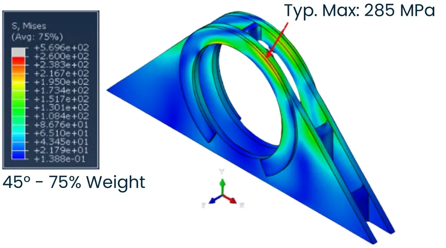
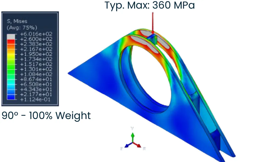
The FEA identified overstressed regions in the existing lifting lugs and trunnion pipe. ENA2 developed targeted strengthening that reduced stresses to within the applicable material yield limits for the specified lifting conditions.
Strengthening measures developed from the FEA results
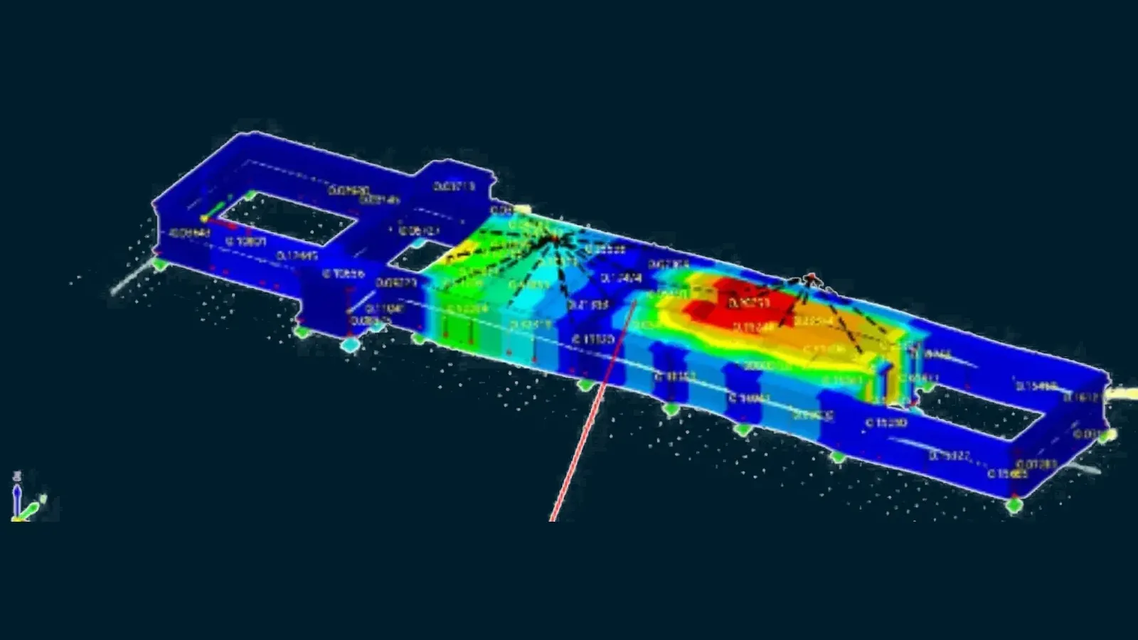
The stress plots show the existing lug at two lifting positions. Based on these results, ENA2 developed:
- Reinforcing pads around the lug holes
- An increased trunnion pipe wall thickness
Both measures target the regions that were overstressed in the existing design.
What This Means If You Are Planning a Heavy Lift
- Check lifting attachments for the specific lift arrangement planned. If the component is rotated, include representative positions through the rotation, not only the starting position.
- Consider out-of-plane loading on lugs when the lift angle changes.
- If an existing lug or trunnion is overstressed, assess targeted local strengthening as an option.
- Ask for the check to cover the lug, the trunnion and the attachment regions to the component, not only the lug plate.
For finite element analysis of other equipment, see our mechanical FEA services and stress analysis services.
More Engineering Case Studies

Lifting Lug and Trunnion FEA FAQ
How do you check lifting lugs and trunnions for a heavy tube bundle lift?
In this project, ENA2 checked the lifting lugs and trunnions with detailed finite element models evaluated at 0°, 45° and 90° lifting positions. Loads were applied to represent bearing contact at the lifting pins or trunnions. Stress distributions were evaluated in the lug plates, attachment regions, trunnion pipe and supporting components.
Why analyze several lifting angles and out-of-plane loading?
In general, the direction of load on a lifting attachment changes as the component rotates, so a single position may not represent the whole lift. In this project, for lifting and rotation from horizontal to vertical, the lifting system was subjected to varying load distributions at different lifting angles, including out-of-plane loading.
What can be done if FEA shows an existing lifting lug or trunnion is overstressed?
One option is targeted local strengthening. In this project, ENA2 developed reinforcing pads around the lug holes and an increased trunnion pipe wall thickness. The analysis showed that these strengthened designs reduced stresses to within the applicable material yield limits for the specified lifting conditions. In general, the right measure depends on the design of each lug and trunnion.
Which lifting standard was referenced in this analysis?
The analysis incorporated factored lifting loads in accordance with ASME BTH-1. The design category, service class and factors used are not published in this case study.
What information should I send for a lifting lug or trunnion analysis?
Send the inputs that apply to your lift, typically the component weight and center of gravity, drawings of the lugs, trunnions and attachments, material information, the lift arrangement and angles to check, pin, shackle and rigging details, and any lifting standard or owner requirement that applies. Scope and schedule are confirmed per project after reviewing the inputs.