Mechanical FEA

FEA Stress Analysis Services

Find out whether a component, assembly or repair carries its loads, where stress and deformation concentrate, and what to change, before you build, modify or return it to service.

Mechanical FEA Consulting

FEA Stress Analysis for Components, Joints and Repairs

ENA2 is a Calgary-based engineering consulting firm providing FEA stress analysis of mechanical components, assemblies, joints and repairs. FEA stress analysis evaluates how a component or assembly responds to the loads it carries: stress, strain, deformation and contact under the operating conditions you define, for new designs and for equipment already in service. We use Abaqus for finite element analysis.

Typical equipment: pressure-retaining parts and nozzles, skids and frames, lifting equipment, bolted and flanged joints, machine components.

01 · Contact

Bolted Joints, Gasketed Flanges and Contact

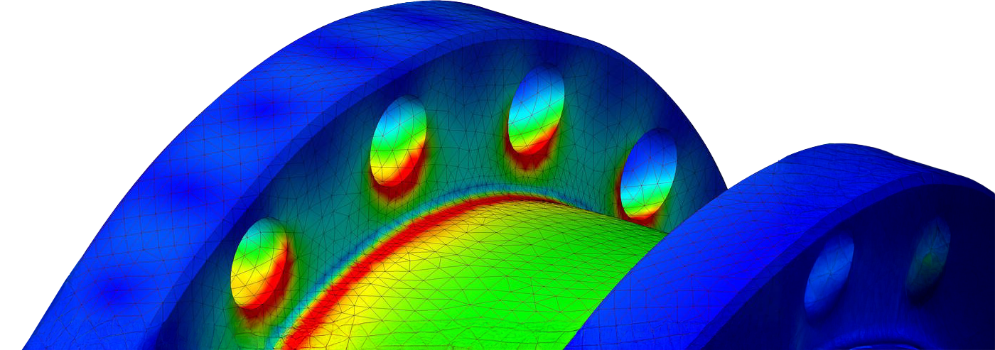
Finite element contact pressure contours between interacting components
Analysis Detail

Contact analysis models how surfaces interact under load at an interface such as a bolted joint, a gasketed flange, a bearing or a press fit, including contact pressure, sliding, separation and friction, and how force transfers from one part to the next.

With bolt preload, gasket and pressure loading in the model, the results show how contact pressure is distributed across the joint and help evaluate whether the joint stays closed under load. They also show the local stress in the bolts and flanges around the contact zone.

02 · Existing Equipment

Modifications, Repairs and Retrofits to Existing Equipment

Repair pad on an existing equipment shell, checked under operating loads
Analysis Detail

A stress analysis of a proposed modification, repair or retrofit on existing equipment models the component with the change in place and evaluates stress and deformation under the operating loads.

Equipment in service is often modified, repaired or retrofitted, and its operating conditions can change over its life. The results help your team decide whether the change is acceptable as designed or should be revised before the work starts. For existing damage, such as a dent or a flaw, see API 579 fitness-for-service evaluation.

03 · Local Stress

Welds, Brackets and Nozzles: Local Stress Concentrations

Finite element stress contours at a pressure vessel nozzle and attachment
Analysis Detail

Peak stress in mechanical equipment often occurs where the geometry or the load path changes, such as at a weld, a bracket attachment or a nozzle.

Static stress and displacement analysis evaluates the stress distribution and deformation of the component under its operating loads and identifies the high-stress regions. The results show where stress concentrates, how far the part deflects and which details govern the response. That gives your team a basis for deciding whether a detail should be revised before fabrication or installation. Where linear results show stress at or above yield, the study can move on to a nonlinear analysis.

04 · Nonlinear

Loads Beyond Yield: Nonlinear and Plasticity Analysis

Equivalent plastic strain (PEEQ) contour showing a local yielded zone on a curved component
Equivalent plastic strain (PEEQ) where the material has yielded
Analysis Detail

Nonlinear analysis is needed to capture the response directly when loads take the material past its elastic limit, or when deformation becomes large.

Linear analysis assumes the material stays elastic and the geometry changes little. We model yielding, plastic deformation and strain hardening using true stress-strain data, together with large deformation and nonlinear contact where they apply. The results show where the material yields and how the component deforms beyond its elastic limit under high loads. This supports the evaluation of components loaded close to or beyond yield.

05 · Load Sequencing

Assembly and Operating Sequences: Load Sequencing

Finite element stress results from a multistage load sequencing simulation
Analysis Detail

Load sequencing analysis simulates how a component responds to a sequence of operational loading conditions, such as bolt preload, pressure ramp-up, thermal cycles and other operational transitions.

It captures how stress redistributes across these stages, from assembly to service. Where contact, friction or yielding is involved, the order in which the loads are applied can change the result. The results show stress and deformation at each modeled stage as well as under the final load.

06 · Thermal Stress

Temperature Gradients: Thermal Stress

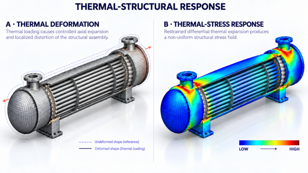
Diagram of a shell-and-tube heat exchanger showing thermal deformation on the left and the thermal stress field on the right
Thermal expansion and the resulting stress field in a shell-and-tube heat exchanger
Analysis Detail

Temperature gradients and restrained thermal expansion add stress to the stress from pressure and mechanical loads.

We use coupled thermal-stress analysis in Abaqus to simulate steady-state and transient thermal loading together with mechanical constraints, and to evaluate thermally induced stress in joints, welds and interfaces. This matters wherever both temperature and mechanical loads drive the design. Where temperature-driven behavior is the main question rather than one load case among several, our thermo-mechanical analysis service covers the broader work.

Tell us about your project

Send a short description and we will propose a scope for your study. You do not need every input ready before you contact us.

What happens next

  1. An engineer reviews your request.
  2. We contact you to schedule a meeting with the engineer or engineering manager who would lead your project, usually within one business day.
  3. Before any project starts, you receive a written scope and quote.
P.Eng. (Canada) or P.E. (USA) stamped reports on request.

Prefer to talk? Call +1 403-910-5957 or message us on WhatsApp. After our first reply, send drawings and models to info@ena2.com.

How It Works

How an FEA Stress Analysis Project Runs

We choose the method from the component, its operating conditions and the decision the analysis has to support. Scope and schedule are confirmed per project after we review the inputs. In most cases, you receive a written scope and quote before any work starts.

01

Define the Question

We agree the component, loads, operating conditions and the decision to support, along with the load cases and any codes the project references.

02

Build the Model

We build the model from your inputs: geometry, materials, contact, boundary conditions and loads, based on your drawings, CAD files and data.

03

Evaluate the Results

We review stress, deformation and contact behavior at the locations that matter for your question, under each agreed load case.

04

Report the Findings

The report sets out the assumptions, results, limitations and recommendations in a form your engineers can review and act on.

Working With ENA2

Engineering You Can Review and Rely On

01

Built around your decision

We model the question you need answered and the report says what we recommend and why.

02

Assumptions you can check

Every report sets out the inputs, the assumptions and the limits of the analysis, so your reviewer can check it.

03

Flow and structure under one roof

Our CFD team can supply flow and thermal loads in the same project, so they reach the stress model without a handover between consultants.

04

Stamped Reports

Reports can be stamped by a P.Eng. (Canada) or a P.E. (USA) on request. Tell us the jurisdiction at the start so it is included in the scope.

05

Confidentiality

We can sign an NDA on request before you share drawings or models. After our first reply, drawings and models are shared by email.

06

Scope of the Analysis

The analysis supports your design and operating decisions. Overall design responsibility stays with the engineer of record.

Scope and Quote

Your Study, Scoped in a Written Quote

Deliverables vary by project

Every analysis is scoped to your project and the question you need answered. Your written quote lists exactly what you will receive; typical outputs include:

  • FEA report with the inputs, assumptions and model description
  • Stress and deformation plots at the locations that matter
  • Contact pressure and joint behavior, where in scope
  • Recommendations
  • The assumptions and limitations of the analysis
Request a quote from our engineering team

What to Send With Your Enquiry

  • CAD files or drawings of the component or assembly
  • Material specifications
  • Loads and operating conditions, such as pressure, temperature and bolt preload where relevant
  • Restraints and supports
  • For existing equipment, inspection findings or details of the proposed modification
  • The question you need answered

If something is missing, send what you have and we will help define the scope.

Questions the Study Answers

What an FEA Stress Analysis Answers

01

Is this component or assembly acceptable under the loads it carries?

02

Where do stress and deformation concentrate, and how much does a design change reduce them?

03

Does this bolted joint or gasketed flange keep its contact pressure through assembly and operation?

04

Is a proposed modification, repair or retrofit acceptable before work starts?

05

How does the part behave beyond yield or under large deformation?

FAQ

FEA Stress Analysis FAQ

What does FEA stress analysis tell you about a component?

FEA stress analysis shows where stress and deformation are highest under the defined loads and how the part or assembly responds to them. Your engineer uses these results to judge whether the design or modification is acceptable.

When is linear analysis enough, and when is nonlinear analysis needed?

Linear analysis is generally enough when the material stays elastic, deformations are small and contact conditions do not change. Nonlinear analysis is needed when the material yields, deformation is large or contact surfaces open, close or slide under load.

What drives the cost of a study?

Mainly the size and detail of the geometry, the number of load cases, whether contact, plasticity or load sequences are in scope, and whether a stamped report is required. In most cases you receive a written scope and quote before any work starts.

We have the software in-house. Why use a consultant?

In-house teams usually call us for one of three reasons: the physics is outside what they run routinely, they need an independent check before a design review, or they need a stamped report. We can also work alongside your team and hand over the model and assumptions.

Can you analyze bolted joints and gasketed flanges?

Yes. We model bolted joints and gasketed flanges with contact analysis, including bolt preload, gasket and pressure loading. Where the assembly order or the sequence of operating loads matters, we apply the loads in stages with load sequencing analysis.

Can you check a modification or repair on existing equipment?

Yes. We carry out stress checks of proposed modifications, repairs and retrofits to equipment in service, modeling the existing geometry with the change in place.

How is stress analysis different from fatigue, fitness-for-service or piping stress analysis?

Stress analysis evaluates stress, deformation and contact under defined loads. Fatigue and fracture analysis addresses fatigue life and crack growth under repeated loading. API 579 fitness-for-service evaluation assesses damage or flaws in operating equipment. Piping stress analysis covers pipe runs, supports and the loads a piping system places on equipment nozzles.

Which software do you use?

ENA2 uses Abaqus for finite element analysis, including the contact, nonlinear and coupled thermal-stress work described on this page.

How accurate are FEA stress results?

FEA stress results depend on the geometry, mesh, material data, loads and boundary conditions that go into the model. The report states the assumptions and limitations, so your engineer can judge where the results apply.

Do you reference design codes, and can reports be stamped?

Where the project calls for it, the analysis can reference ASME BPVC Section VIII, Division 2 (Part 5, design by analysis) or API 579-1/ASME FFS-1; the codes and acceptance criteria are agreed for each project. Reports can be stamped by a P.Eng. (Canada) or a P.E. (USA) on request; tell us the jurisdiction at the start.

Where is ENA2 based and which regions do you serve?

ENA2 is based in Calgary, Alberta, and works with clients across Canada and the USA.

Mechanical FEA

Have a Stress Analysis Question?

Send your drawings, loads and the question you need answered, and we will propose a scope. You do not need every input ready before you contact us.

Scroll to Top